- PRINCIPLE:
Conventional lifting systems exert a high differential pressure on the oil producing formation allowing an easier water flow thereby creating high water saturation around the wellbore. This saturation prevents a satisfactory flow of oil and results in such a high level of water production that a well becomes uneconomical to exploit.
Our technology functions in tubing and sucker rod free casing and simply bails out the oil encountered in the fluid column which is naturally driven towards the well by the pressure of the reservoir. Our fully automatic mechanical system lowers a hollow collector tube connected to a wire line into the oil column at a predetermined immersion depth and then lifts it up to the surface to be drained off.
- CYCLE DESCRIPTION:
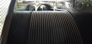
- A hollow cylindrical collector tube made of stainless steel connected to a steel wire line is lowered through the well casing (free of tubing & sucker rods) by means of a mechanical lifting device connected to a revolving wheel on which the wire is coiled.
- The fluid level is automatically detected and the collector tube is slowly immersed at a programmed depth below this level (approximately 50 feet).
- The collector tube becomes filled with fluid recovered from the top of the liquid column passing through a bottom check valve
- The oil filled collector tube is then lifted up to the surface at high speed until it arrives close to our patented wellhead.
- The system is programmed so that the upper part of the filled collector tube enters the wellhead slowly until the opening of the 1”1/2 stainless steel tube reaches the suction level of a 4HP Moyno type pump.
- The pump is then activated by means of a sensor and suctions and discharges liquid & gas towards a storage facility or a conduction line.
- When the oil has been totally drained from the collector tube the pump is deactivated by means of a sensor, the brake securing the main wheel is released allowing the collector tube to be run back into the well and a new cycle is so reinitiated.
- During the three phases of descent, filling and lifting out of the collector tube, the gas inside the casing is discharged towards the conduction line through a gas outlet located at the upper part of the wellhead.
- This gas discharge occurs while the wellhead internal pressure exceeds that of the conduction line. In such, natural gas pressure can be taken advantage of in optimizing the fluid extraction process (in allowing, in particular, to use longer collector tubes).
NOTES:
- The system is programmed so that the collector tube follows the descent of the fluid level during the initial period of the test until the fluid extracted compensates the fluid produced by the formation. At that stage a “balance point” is attained and the collector tube will no longer descend.
- Driven by reservoir pressure, the oil naturally migrates from the formation towards the well bore to recharge the fluid column while the oil-filled collector tube is surfacing. See our animation
